
The ADR series of linear motor XY microscope stages is one of the most application specific products I’ve developed. The goal of this project was to design the best stage in the world for 24/7 high throughput imaging with a form factor that can be mounted to conventional inverted microscopes from “the big 4”.
Primary goals were to provide similar baseline functionality to the existing ASR series, but with maximized performance in 3 main areas:
- Accuracy and repeatbility
- Throughput
- System reliability
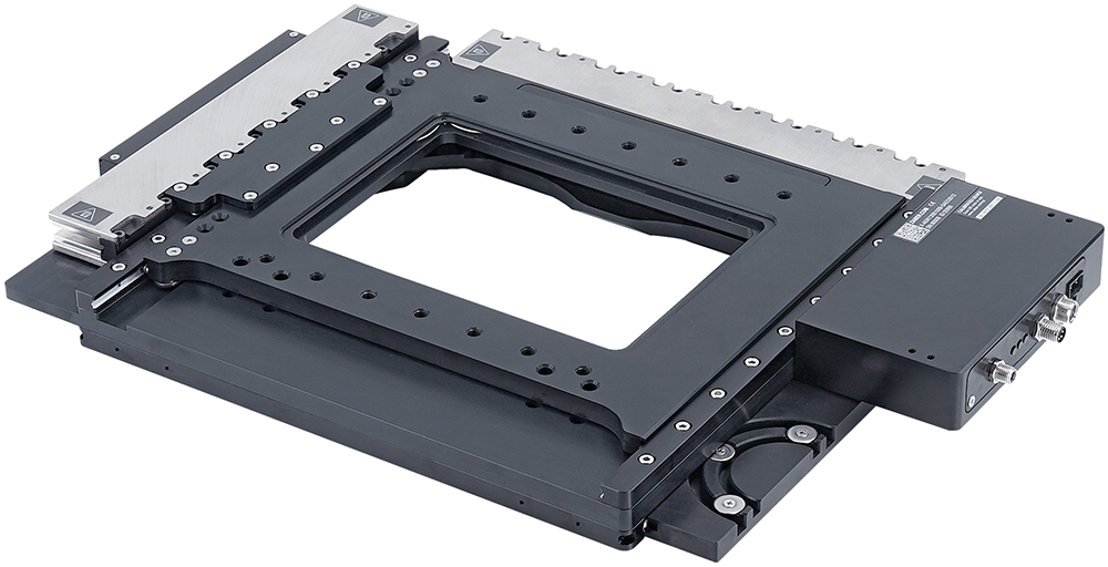 The smaller of two stages in the family, 130mm X 100mm travel
Design
The ADR design uses similar aspects from the LDM design. Primary components include:
- Linear crossed-roller bearings.
- Ironless linear motors.
- Optical linear encoders.
See the LDM design for detailed information about these components. One crucial difference with the ADR is that it uses an in-house designed linear motor. This resulted from the realizations that 2 linear motors are incredibly expensive, and that high thrust typically isn’t needed for a microscope stage moving light payloads around, so a motor optimized for max force density isn’t required. I can’t say how we made these motors, but I can say that they are far cheaper than anything available on the market, and have remarkably comparable performance.
Stage Layout
One key aspect of the ADR design is that the short travel axis is on top. This was done to make one axis as light (and fast) as possible, because raster scan algorithms move primarily in one axis. Both motor forcers and encoder readheads are located in the mid-plate assembly to eliminate reliability concerns due to moving cables. For maximum speed it would have been optimal to have the upper forcer move with the top-plate, but this was considered a reasonable trade-off for improved system reliability.
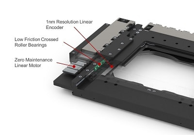 Layout of components in the ADR upper axis
Features
One great aspect about the integrated controller on this stage is that it allows power and data to be run through one cable. In this case it becomes the only moving cable in the system, and can be swapped in minutes in the case of a lifetime failure. The stage also includes cable management features integrated into the base-plate, allowing for clean cable management with sufficent bend radii.
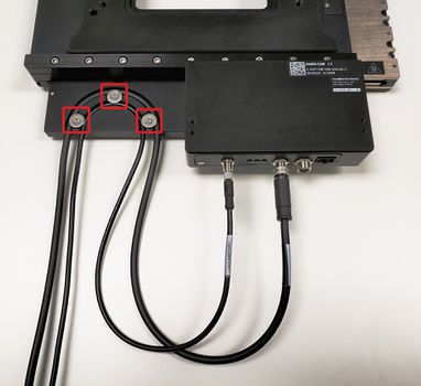 The ADR features integrated cable management for strain relief
The ADR also includes adjustable +/- hard stops on each axis. Travel limits can be set in firmware, but these provide extra reassurance to protect delicate samples or optics.
The ADR also features a unique magnetic constraint system for restraining inserts in it’s standard 160mm X 110mm aperture. To my knowledge this is the first system of it’s kind in a microscope stage, and makes automated insert changes far more convenient.
Performance
Performance of the ADR stages is remarkable compared to the ASR. Full travel calibrated accuracies of 1µm are readily achievable, which is at the threshold where image stitching algorithms may not be required because all the pixels line up perfectly. Repeatability falls around 500nm due to wide spacing of the bearings and offset between the sample and encoder. The stages can comfortably perform 50nm moves as shown below, which is already well below the resolvable diffraction limit of visible light.
With a bit of servo optimization, these stages can perform small movements incredibly quickly, as is typically needed for image stitching applications. High axial stiffness is a huge benefit of linear motor systems, allowing much higher servo bandwidth and thus faster response times than other systems. An additional benefit is that position is constantly being monitored at 1nm resolution, so the system will never report that a move is complete until vibrations have actually died out. Blurry images would result from systems without active position monitoring.
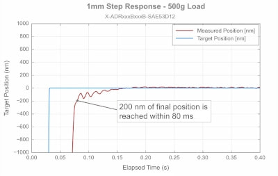 System response for a 1mm move
Lessons learned
No project is complete without recognizing what you’ve learned along the way.
- The influence of bearing aspect ratio.
- One will notice the bearings on this stage are spaced very far apart (out of necessity). Originally we guessed this would lower yaw stiffness. It doesn’t actually lower yaw stiffness, but rather yaw repeatability, which manifests as slight backlash.
- Slowing down often speeds up cycle times.
- For low vibration applications, moving faster is often worse because it results in higher residual vibrations, the decay of which actually increases the overall cycle time. Control systems theory should be utilized to determine the optimal trade off between speeding up and increasing vibrations.
- Designing multi-axis systems is exponentially more complicated.
- A 2 axis system is more than 2x as hard to design. Servo optimization was particularily challenging because system resonances would change depending on the combined position of both axes.
Conclusion
The ADR microscope stage is an exciting addition to the world of high throughput imaging. It will be interesting to see if this technology becomes the gold standard.
Note: The content of this article is intentionally limited to respect confidential information of Zaber Technologies.
