
This project consisted of an alignment and visualization system for a series of industrial robots in the BMIT beamline at the Canadian Light Source. It was featured in the AIP Conference Proceedings 1741 in 2016.
Background
Aligning samples at BMIT has always been a problem. The invisible X-ray enters the experimental room at an angle defined by it’s energy. At least 3 different systems need to be robotically aligned to the beam with high precision: the entrance shutter, the sample positioner, and the camera positioner. To further complicate things, the sample needs to be aligned with it’s rotary axis highly perpendicular to the X-ray (within 1 pixel of the camera). The sample positioner is based off a kappa goniometer which also has complex kinematics.
To simplify this alignment process, it was desired to develop a visualization system and implement kinematics to calculate alignment geometries.
 The BMIT 05ID-2 experiment room. The X-ray travels from right to left.
Implementation
A detailed SolidWorks model was first put together of all key system components. Global variables in the SolidWorks model were then linked to all aspects of it we would want to control, including robotic axes, beam size, sample size, etc.
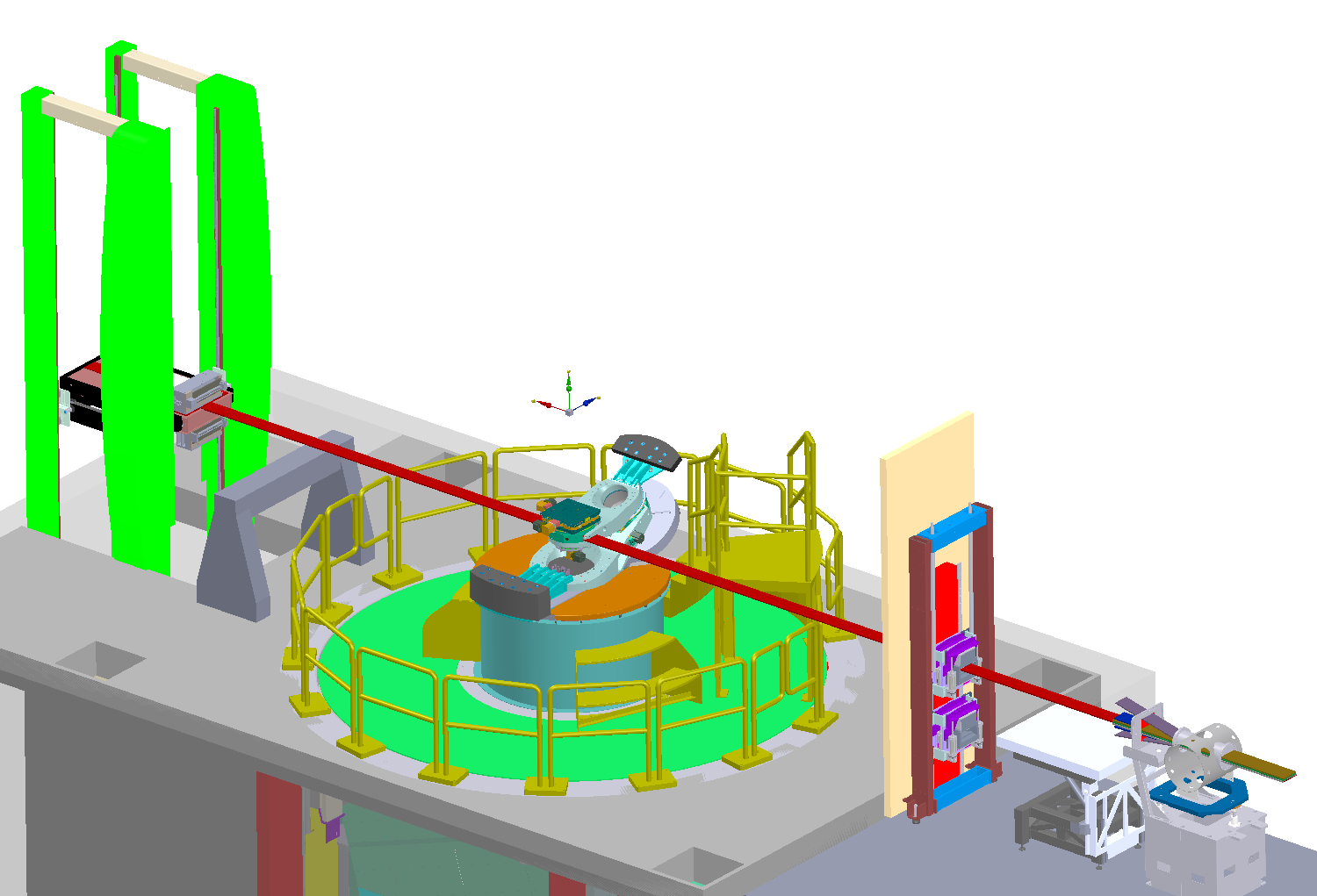 CAD model of the system. The x-ray is shown in red. The beam angle is determined in the round vacuum chamber in the bottom right.
Software was then written to automatically adjust these model variables using the SolidWorks VB.net API. This software also included functions to adjust the model view, rotation, zoom, etc. and export images of the model as well as various geometry measurement functions. A TCP server was then added to the software, allowing it to receive commands from any computer on the network and return images of the model. The software was designed so it could open multiple instances of SolidWorks in the background, allowing multiple computers to connect and adjust different configurations of the model.
The final aspect of this project was to develop inverse kinematic equations for the kappa goniometer, allowing us to align it based on beam geometry. These equations were built into a python package by one of the control systems engineers, allowing it to calculate desired system geometries, adjust the SolidWorks model remotely over TCP, then return images of the configuration.
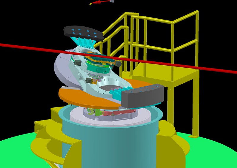 An example image output from the server. Sample alignment geometries can be complex.
Project Poster
Below is a posted about this project. It is also available in pdf format.
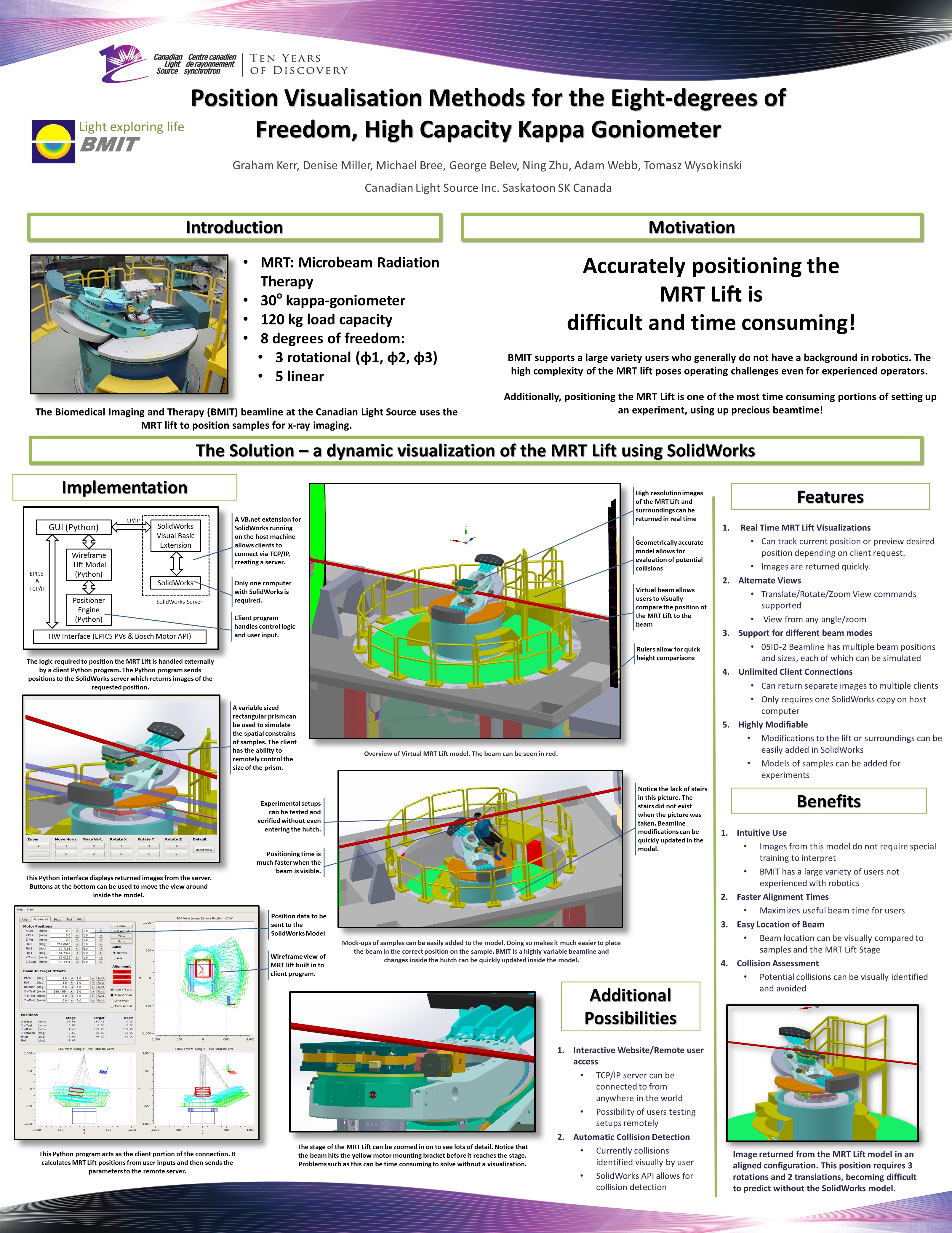 Download for higher resolution
