Input shaping is an extremely interesting technology. It offers significant productivity gains in the field of motion control with almost no cost. Sound too good to be true? Surpringly, input shaping is a topic that gets very little attention. As of writing this article, the Wikipedia Page on input shaping has a mere single paragraph explanation.
I’ve already written a relatively detailed article on input shaping: Input Shaping for Motion Control Vibration Reduction. However, this topic has so much merit I’ve felt inclined to write an article here to cover more things not suitable for technical note.
Overview
So what is input shaping? In reality, the gist is relatively simple:
- Objects tend to vibrate at a certain frequency (or frequencies).
- Determine what those frequencies are.
- When you move the object, move it in such a manner that doesn’t excite those frequencies.
- The object will vibrate less when you stop, allowing you to do things faster (ex. take a picture without blur).
What does this actually look like? Check this out:
Preventing liquid spills is a highly useful application for input shaping
Note that not only does the water stop sloshing, but the motion is also faster! This is a major win for something as simple as tweaking the trajectory.
Interesting Applications
Let’s start with the cool stuff! Here are some applications of input shaping that I consider to be particularly interesting and relevant.
3D Printing
The use of input shaping for 3D printing is particularly exciting because I see it as the first mainstream implmentation of the technology. This pretty cool considering the gold standard paper on input shaping was published over 30 years ago! Until quite recently a google search on input shaping would return only academic papers, which are now replaced with hobbiests discussing the performance of their printers.
Over the past couple years it’s become the norm for medium to high end 3D printers to support input shaping. I believe one of the big first adopters was Klipper, an open source 3d-Printer firmware. Their cheap performance gains were so advantageous they’ve driven many other companies to follow suit.
So why is input shaping such a big deal? The answer is that vibrations create print defects, and input shaping allows increasing print speeds without introducing defects. See the video for examples:
Print quality improvements from input shaping make it a no brainer given the low cost
The low price targets of 3D printers also make input shaping particularly enticing. Why waste money making your printer stiffer when you can solve the problem at the software level?!
Cheap accelerometers are another key technology paving the way to adoption. Complete USB powered PCBs with sensors like the ADXL345 are widely available for around $20. This means that an intelligent 3D printer can easily measure it’s own resonances in situ with the occasional calibration routine, providing far better performance than a preset factory calibration.
More information on Klipper can be found below:
Cranes
Cranes are an excellent case study for input shaping because the low frequencies allow easy visualization of the theory. Cranes are actually one of the oldest applications of input shaping. You’ve probably watched them your whole life and never thought twice about why payload swaying isn’t a problem. While it’s easy to chalk this up to operator skill, the reality is that the crane’s control systems handle this on the fly automatically.
Below is an example demonstrating input shaping on a dual hoist crane. This implementation is slightly different due to the dual trolleys, but the underlying theory is identical.
Georgia Tech is the source of many excellent input shaping papers
One interesting point demonstrated in this video is that input shaping can be used “in reverse” to intentionally amplify vibrations. This is akin to a human pumping on a swingset, and although clearly less practical, is cool demonstration of the technology.
It’s also worth noting why cranes are inherently well suited for input shaping. The key is that there’s typically a single dominant resonant frequency, and it can be determined with relative ease:
- The spool motor can track the length of extended cable.
- A loadcell can measure the attached payload weight.
- If the cable is assumed to have neglible weight this isn’t actually required, but improves the estimate.
- The resonant frequency can be estimated with equations for a compound pendulum.
While the typical crane is quite simple, there has also been a lot of research into more advanced cases such as dual pendulum configurations or gantry cranes where additional yaw rotational frequencies may exist.
Multi-Dimensional Robot Arm Control
Most input shaping applications are done in one dimension. Even for multi-axis systems (ex. XYZ), each direction is normally treated independently. However, this example from The No Spill Project shows a far more complex (but very elegant!) multi-DOF example. It combines input shaping on all 6 degrees of freedom simultaneously to prevent a cup of water from spilling.
Multi-DOF input shaping as shown here is cutting edge
It should be noted that this example isn’t “conventional” input shaping; the underlying theory is different because it relies on minimizing tangential forces on the liquid rather than moving away from the resonant frequency. However, the general principle is the same: the motion trajectory is modified in a clever way to produce a result with reduced vibration.
Additional details on the project can be found here:
- Paper: A Solution to Slosh-free Robot Trajectory Optimization
- Paper: Geometric Slosh-Free Tracking for Robotic Manipulators, Source Code
The general theory behind this slosh control algorithm is relatively simple, but the implementation is impressive
Theory
So you want to learn input shaping? There are quite a few useful learning references below.
However, there’s also a lot of key foundational material that’s missing from existing input shaping content on the web. The goal this section is to elaborate on some of these aspects that I consider to be non-intuitive and generally aren’t explained well.
Frequency Dependence
One of the biggest fundamental aspects I consider easy to overlook is the importance of input frequency on vibrations. Everyone intuitively knows that shaking an object harder (larger amplitude) will cause it to vibrate more. What’s less intuitive is that adjusting the speed of shaking (frequency) also has an equally significant effect.
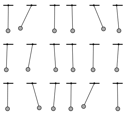
Consider the animation below. Three pendulums are swung at the exact same amplitude, but with different frequencies. The middle pendulum vibrates drastically more because the input frequency is near it’s resonant frequency. If we were trying to move the pendulum at this frequency we’d have vibration problems, but we could speed up or slow down to get much better results.
 Three identical pendulums excited with the same amplitude, but different frequency.
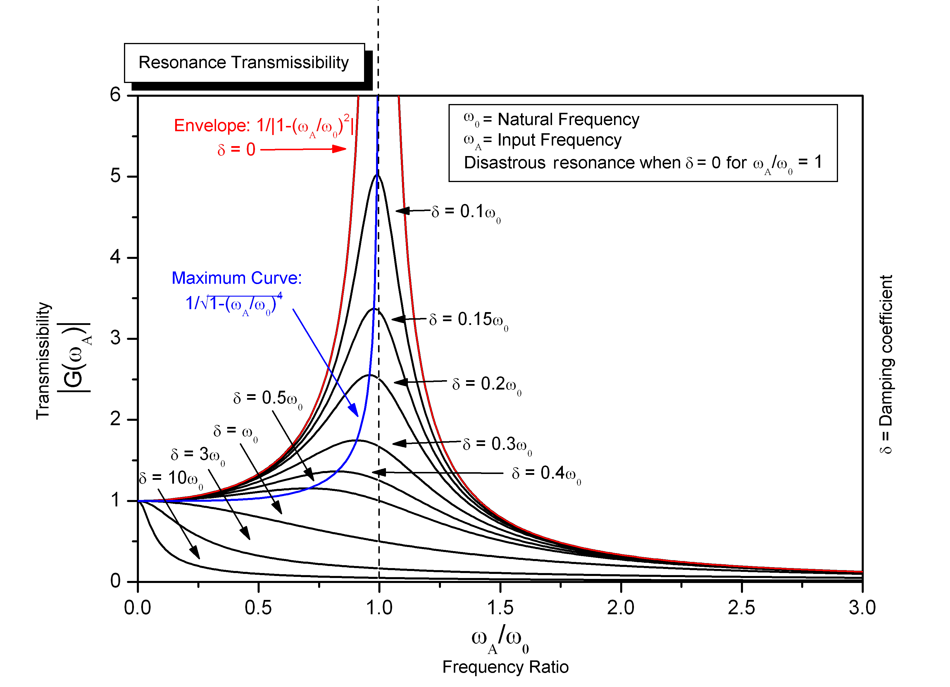
The behavior of these pendulums is plotted below on a transmissibility curve.
- At low input frequencies (slow shaking), the resulting vibration almost perfectly matches the input.
- As the input frequency approaches the resonant frequency, the vibration gets very large.
- As the input frequency exceeds the resonant frequency, the vibration starts to decrease again, eventually approaching zero.
If this doesn’t make sense to you, try shaking something flexible like a metal ruler at different speeds and see if you can replicate the curve.
 Behavior of the animated pendulums plotted over many input frequencies. The middle case occurs at a frequency ratio of 1.
This plot visualizes the most important principle of input shaping; if you move an object at frequencies near it’s resonant frequency, you’re going to have vibration problems. Another key realization is that we have two options to solve this: speeding up or slowing down!
It should be noted that adding damping will also reduce vibrations, as can be seen from the many curves plotted above for various damping ratios. But why would we waste money on damping when we could simply move faster instead?! This realization is one of the reasons input shaping is such an elegant solution.
Fourier’s Theorem
So you get it: to avoid vibrations, don’t move objects at their resonant frequency. But you don’t want to shake your object with an amplitude and frequency; you just want to move from point A to B. How is this theory still relevant?
The theory above only applies to inputs that are a sine wave. But this generally isn’t the case for most motion trajectories! Thankfully, Fourier’s theorem is to the rescue:
- A periodic function f(x) which is reasonably continuous may be expressed as the sum of a series of sine or cosine terms (called the Fourier series), each of which has specific amplitude and phase coefficients known as Fourier coefficients.
What does this actually mean? Essentially, it means we can represent any curve with sine waves. This might be hard to believe, but check out the example below: we can produce a highly complex function just by adding four sine waves together!

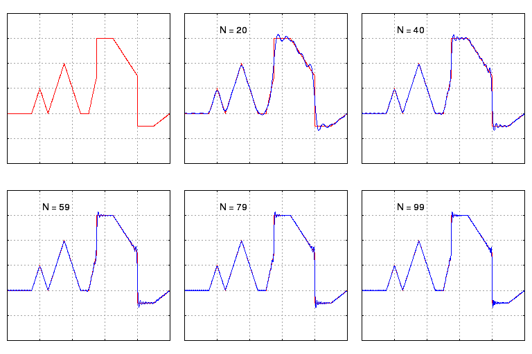
Still skeptical? The next example shows how we can represent a highly complex function with sine waves. If we added infinite sine waves together we’d be able to match the line perfectly.
 Even complicated functions can be represented by sine waves.
While Fourier’s theorem states that we need infinite sine waves to perfectly represent any curve, a key observation is that we can get pretty close with only a few sine waves. What this ultimately means is:
- To represent a curve with sine waves, there are ususally a few dominant frequencies with large amplitude, and the rest have relatively small amplitude.
It may have clicked by now, but if not: we better make sure that none of the dominant sine wave components have frequencies near the object’s resonant frequency.
To summarize, because any curve can be represented by sine waves, the input shaping theory for sine waves also works for any curve.
Implementing Real Trajectories
So how do we actually go about input shaping for real trajectories? There are a few important points:
- Vibrations are induced by forces acting on the system.
- Forces are proportional to acceleration (F=ma).
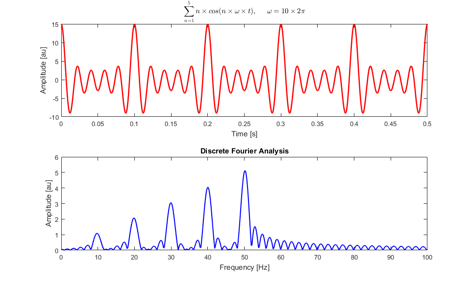
- The fast fourier transform (FFT) is an easy method to decompose a function into it’s sine waves (frequency components).
 The FFT extracts frequency components (sine waves) from a time series signal.
Therefore, to determine if a trajectory will cause problematic vibrations:
- Compute the trajectory (position vs time).
- Differentiate it twice to get acceleration vs time.
- Multiply by the mass to get force vs time.
- Compute the FFT of the force vs time signal.
- Compute the spectral density of the FFT (amplitude vs frequency).
- Confirm that regions of the frequency spectrum near the resonant frequency have small amplitude.
That’s it! If the FFT amplitude is large near the resonant frequency, there’s a significant sine wave component around that frequency and we’ll get bad vibrations. See here for examples of this in practice.
Input shaping algorithms are just fancy methods of performing this process in reverse: target low magnitudes around the resonant frequency and work backwards to find a trajectory that accomplishes it! However, you can get a sense of how this becomes complicated quickly, for example if we wanted to target multiple resonant frequencies or enforce specific performance constraints on the trajectory.
Relationship with Servo Tuning
This section is included to avoid a common pitfall of the aspiring engineer: “I need my machine to do x faster, so I need better servo tuning”. While this is true, servo tuning is only half the battle: input shaping is equally important!
- Get your servo tuning decent, then focus on input shaping.
- Servo controllers have their own resonant frequency. This could be significant in additon to the system’s mechanical resonances. If so, make sure the input shaping works for both frequencies.
Useful References
Here are some useful references to learn more about input shaping. Most of these are mentioned in the article, but are also included here for convenient reference:
- Kerr, G. (2022): Input Shaping for Motion Control Vibration Reduction
- Singer, N. C., & Seering, W. P. (1990): Preshaping Command Inputs to Reduce System Vibration
- Singh, T., & Singhose, W. (2002): Tutorial on Input Shaping
- Conker, C., Yavus, H., & Bilgic, H. H. (2016): A review of command shaping techniques for flexible-joint manipulators
- Huey, J. R., (2006): The Intelligent Combination of Input Shaping and PID Feedback Control
- NASA (1995): Minimizing Structural Vibrations with Input Shaping
- Klipper 3D: Resonance Compensation