
The LDA series of compact direct drive stages was a project I managed the development of throughout 2019. The goal of this project was to retain as much of the precision of the LDM series stages as possible while significantly shrinking the form factor, further expanding Zaber’s offering for easy to use nanometer level precision stages.
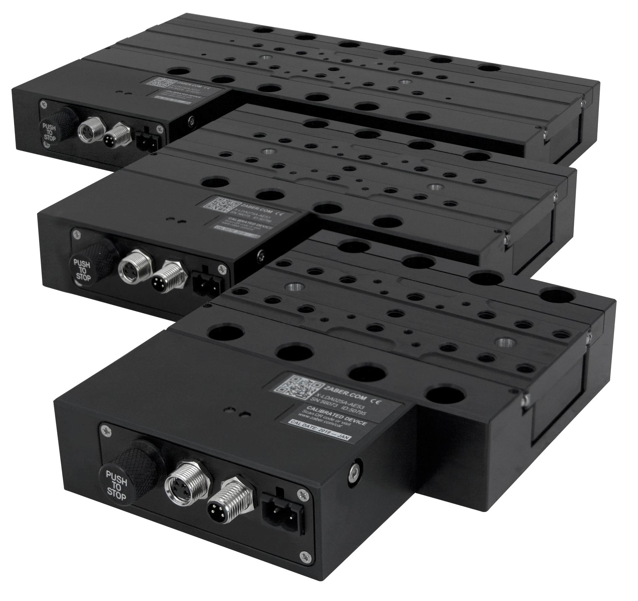 LDA stages are offered in 3 travel lengths: 25, 75, and 150mm
Design
The LDA design re-uses many aspects from the LDM design. The 3 main components are similar:
- Linear crossed-roller bearings.
- An ironless linear motor.
- An optical linear encoder.
See the LDM design for detailed information about these components. Primary differences with the LDA are that a much smaller motor and encoder were used. This significantly lowers the thrust output, and slightly lowers the precision for small moves (less than 20µm) due to higher sub-divisional error from the encoder.
Stage Layout
The LDA uses a more conventional linear motor stage design with the motor in the center of the stage. As described in the LDM design, this is most space efficient layout but significantly weakens the base and carriage. The lack of stiffness was mitigated by placing the bearings as high in the stage as possible, creating bending loads on the base but pure compression loading on the carriage.
Bending forces in the base make the base substantially less stiff than the carriage from a bearing preload standpoint. However, bolting the stage to any semi-rigid surface such as a 1/2” breadboard solves this problem completely. The base has narrow mounting pads to ensure uneven mounting surfaces have as little effect on bearing preload as possible, however LDA stages are far more sensitive to uneven surfaces than LDM stages.
The high bearing placement also results in a very thin aspect ratio carriage. Particular care had to be taken to develop a machining process which would yield sufficent flatness tolerances on bearing mating surfaces along the length of the carriage.
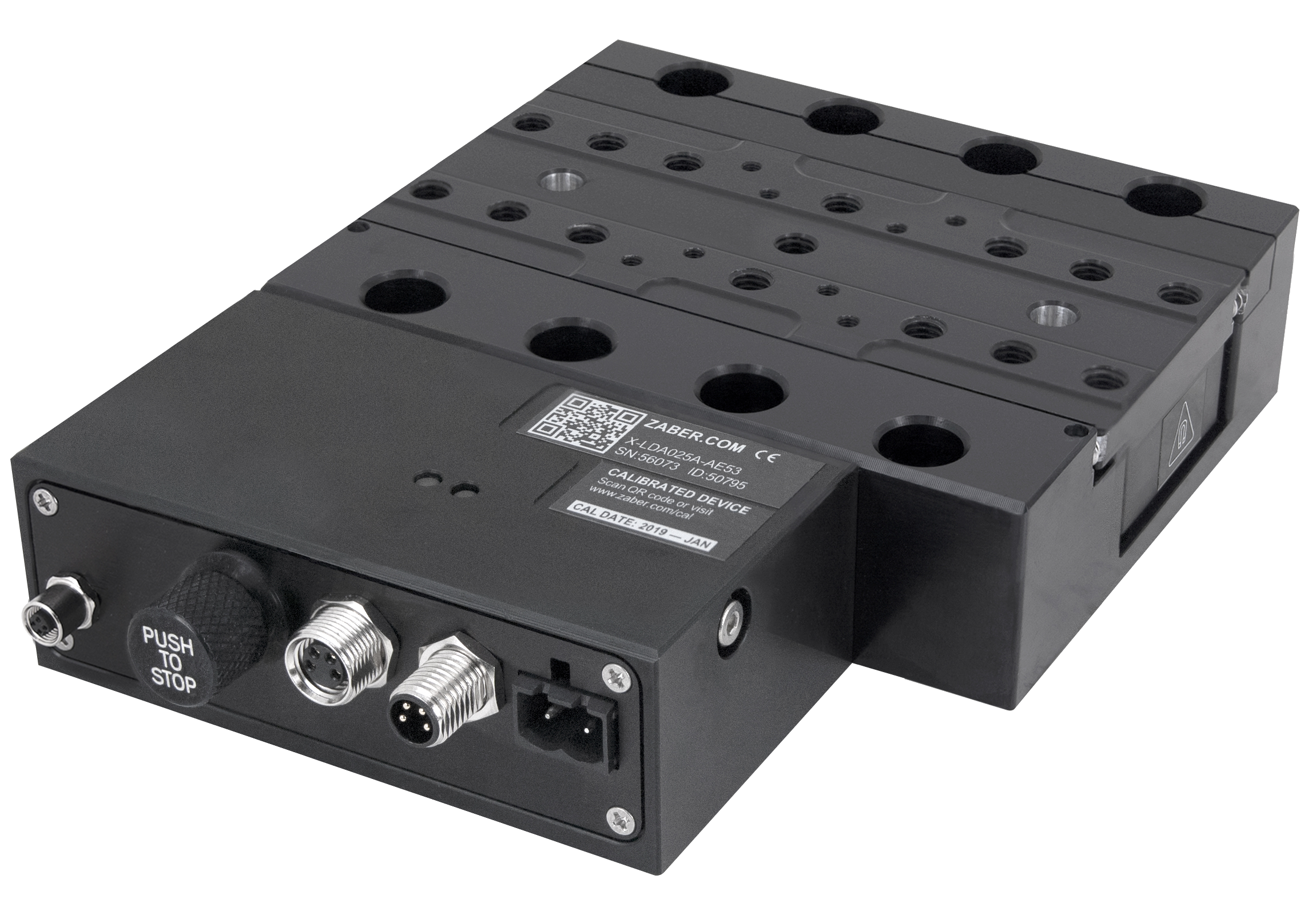 The central motor in the LDA is the most space optimal configuration
Mounting Features
The LDA design was based around M6 mounting holes on a standard 25mm breadboard grid pattern, a unique feature compared to similar stages. This was a design decision intentionally chosen to favor Zaber’s “Lego brick” modular ecosystem over smaller M3 or M4 mounting holes, which would have resulted in a smaller form factor and potentially a more OEM friendly product. Breadboards are extremely common for photonics applications where stages like the LDA are typically used, and direct mounting simplifies integration while also providing optimal flatness and parallelism by removing the need for adaptor plates.
XY Assemblies
LDA stages are designed to bolt directly together in XY configurations, or on top of LDM stages. Again, direct mounting is ideal for optimal flatness and parallelism. Similar to the LDM, the carriage and base include holes for dowel pins to obtain orthogonal alignment. These down pin features are designed to mate directly with other LDA or LDM stages.
The LDA/LDM XY configuration is particularly notable for high speed applications. This configuration is optimal due to the LDM’s high thrust, stiffness, and the LDA’s low mass.
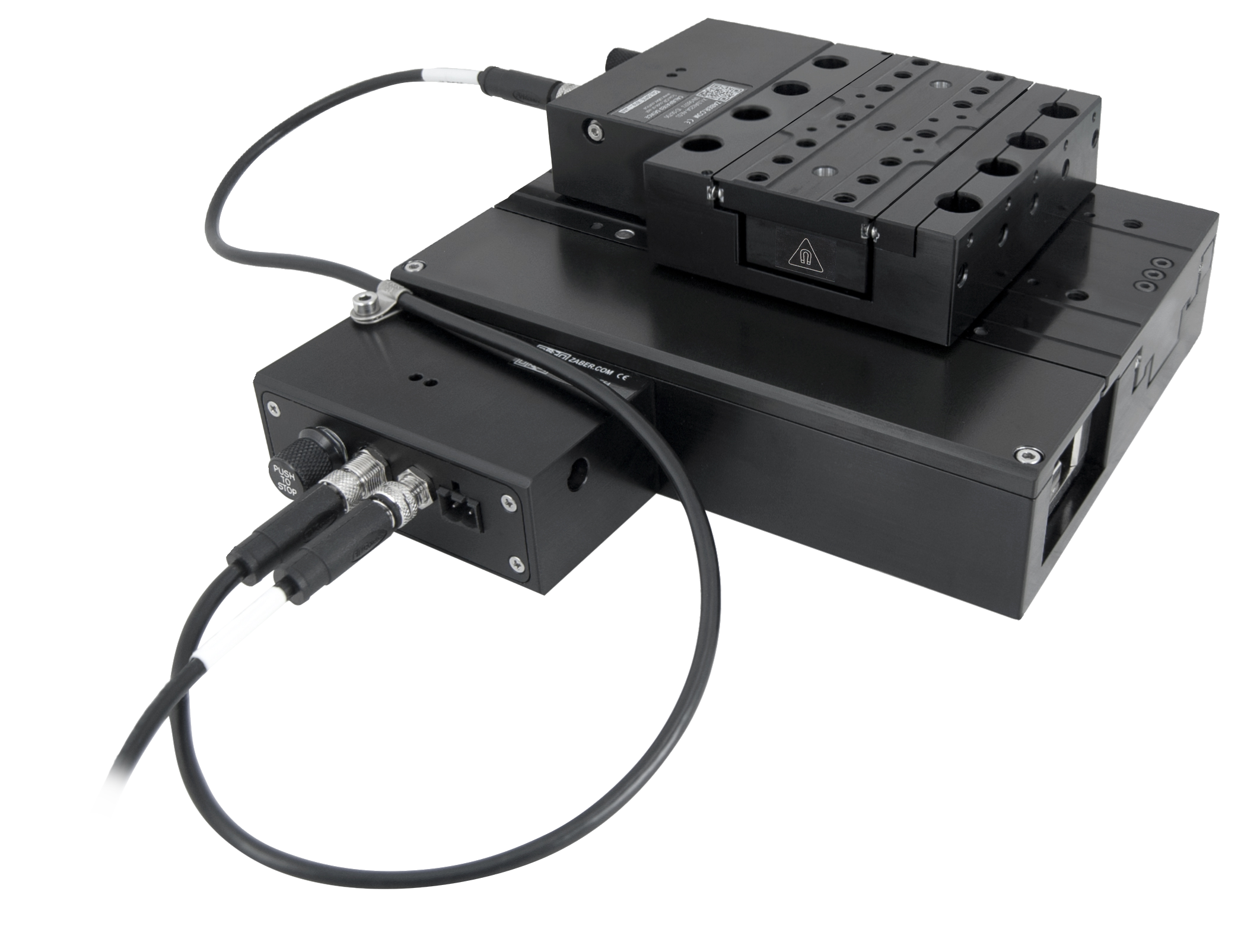 An LDM060/LDA025 XY configuration. This setup is optimal for high speed applications. The integrated controller requires only a single cable between the stages.
Performance
Performance of the LDA stages is suprisingly very comparable to the LDM. Full travel calibrated accuracies of 500nm are readily achievable. However, the design isn’t as thermally stable because the encoder is placed right next to the motor, and also probably because the thermal mass is much lower. Repeatability also suffers (200nm vs 80nm) due to the lower system stiffness and shorter bearings used in the design.
 Full travel accuracy plot of an LDA150
In-position jitter falls around 4nm RMS measured at 20KHz with laser interferometer. Surprisingly this is actually better than the LDM. Initially it was suspected that jitter would be worse on the LDA due to the tiny motor’s low inductance amplifying the driver’s 40KHz PWM ripple. It is suspected that the decreased jitter is due to the motor’s lower force constant (3.7N/A vs 15N/A) amplifying the current sensor noise less. What likely matters most is the ratio of motor force constant to moving mass, however the role of bearing drag must also be considered as it acts similar to a spring at such small displacements.
Jitter limits the minimum incremental move (MIM) to around 20nm based on NIST’s evaluation criteria. stages. The low noise current sensors on Zaber’s X-MCC external controller decrease the jitter to around 2nm RMS and the MIM to 12nm.
Lessons learned
No project is complete without recognizing what you’ve learned along the way.
- Be aware of diminishing returns for engineering trade-offs.
- The height of the LDA stage is 31mm. There are numerous discussions about how it would be nice to get the stage height down to an even 30mm. Ultimately I made the decision that reducing the height to 30mm would weaken the already flimsy carriage and base too much. Losing robustness of the design isn’t worth 1mm, which probably wouldn’t affect many customers in the long run anyway.
- Always future proof whenever possible.
- The XY alignment dowel pins on the LDM were designed to butt up against the edge of the stage for maximum user simplicity. This works great, but was tough to integrate with the LDA and ultimately required dedicated features just for LDM compatibility. The LDA has a more interoperable design with both dowel pin holes located along the center of the carriage.
- Test devices in harsher environments than are expected for normal use.
- Intentionally slamming the LDA carriage into the end of travel as hard as possible revealed that the bump stops could shift out of position, resulting in a screw eventually hitting the motor and damaging it. At the time it felt harsh to treat a precision product so poorly, but it revealed a weakness that likely would have eventually cropped up when a customer lost power with a heavy payload attached.
Conclusion
The LDA series stage lineup nicely complements the LDM series stages to fill out Zaber’s high accuracy stage offerings. Precision specs are very comparable to the LDM with a significant size decrease. This project was particularly fun because it allowed application of many lessons learned during the LDM project. There are many subtle details in the LDA design that were inherited from things I wished I could’ve re-designed on the LDM. In particular, LDA stages are much easier to assemble because of these design improvements.
Note: The content of this article is intentionally limited to respect confidential information of Zaber Technologies.
