
The LDM series of linear motor stages was one of my first projects as a lead product manager. The goal of this product lineup to lower the barrier to entry for ultra-precision nanometer level motion control. Due to the integrated controller, these stages are the first stages in the world capable of single nanometer movements that can also be set up in seconds. It’s remarkable to plug in one of these stages and immediately command 25nm movements with the knob.
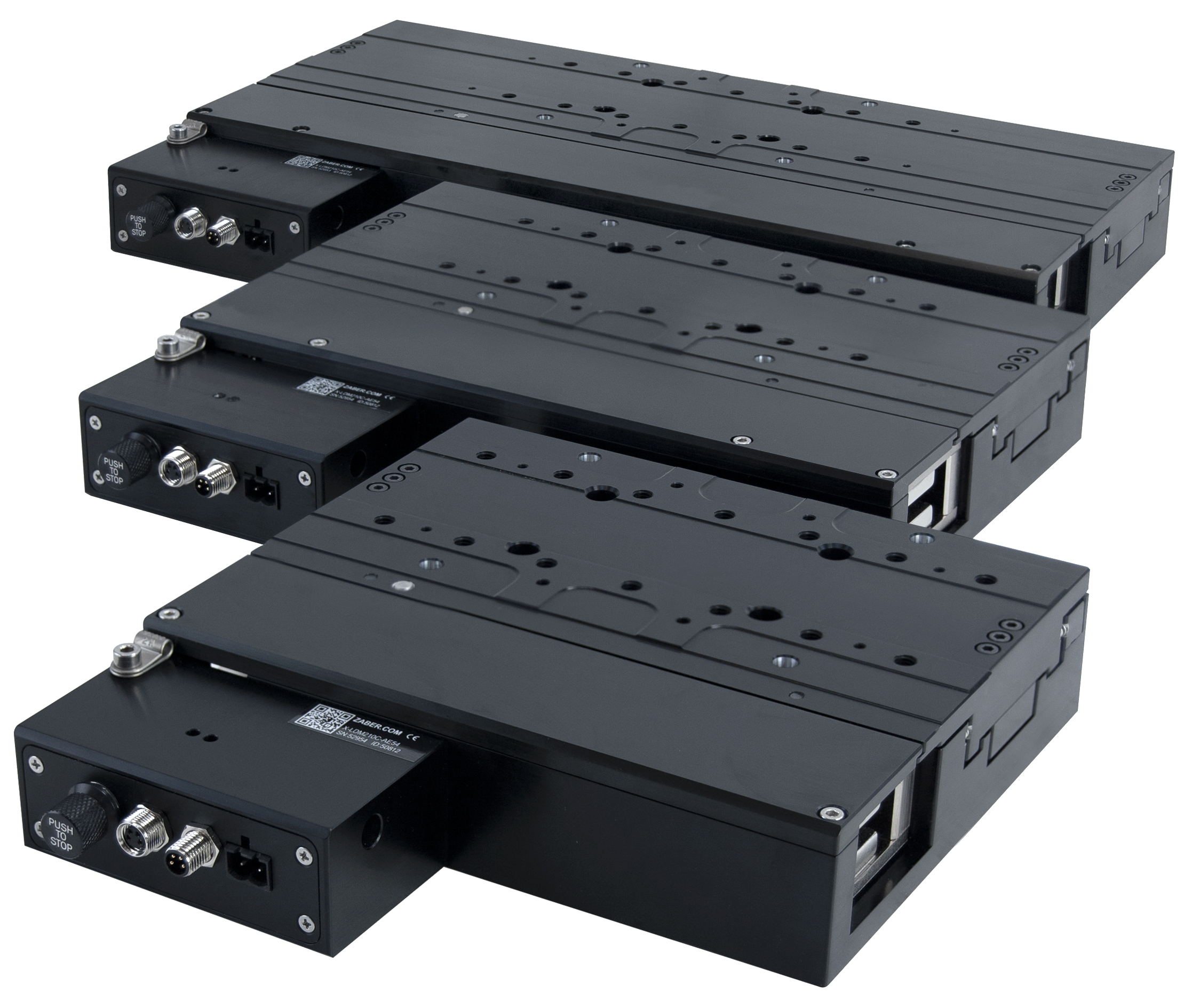 LDM stages are offered in 3 travel lengths: 60, 110, and 210mm
High Level Design
The LDM design revolves around utmost precision. There are 3 key components to the design:
- Linear crossed-roller bearings.
- An ironless linear motor.
- An optical linear encoder.
With the exception of air bearings, these components are about as good as it gets for high precision applications. Air bearings were ruled out due to their cost and lack of user-friendliness (air supply, ease of damage, etc.).
Crossed Roller Bearings
Crossed roller bearings have a few primary features that make them excellent for this type of application:
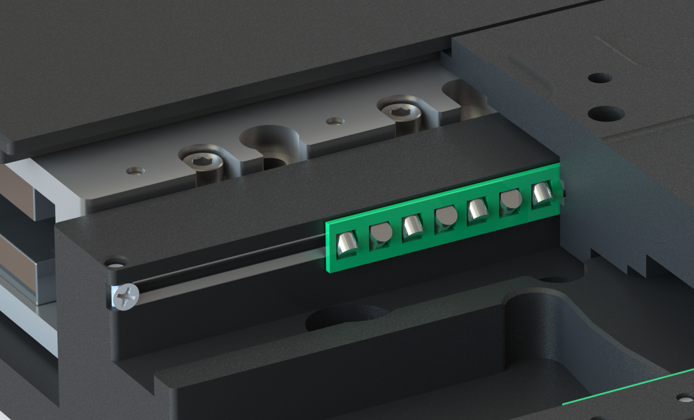 Cutaway render displaying crossed roller bearings in the LDM
- Low and highly consistent drag force.
- Excellent repeatability.
- High stiffness.
Low drag force is a big deal for increasing the speed of small movements, which are common in optical applications. The final phase of a motion is usually dominated by the servo controller’s integrator. Increased drag and stiction means that the integrator takes significantly longer to spool up and correct small errors (usually under 1 micron). Additionally, consistent drag force means that servo controller feedforward parameters can be tuned quite accurately to compensate for what little drag exists evenly across the full travel range, further decreasing movement times. Consistent drag force is also crucial for decreasing following error during constant velocity moves because the servo controller doesn’t have to constantly adjust.
The positional repeatability of crossed roller bearings is also excellent. The lack of recirculating elements means that each roller always ends up in the exact same location on the bearing race. Repeatbility under 250nm can easily be obtained. High stiffness also ensures that subtle variations in drag force or loading conditions have minimal effect on repeatbility or angular runout.
Ironless Linear Motors
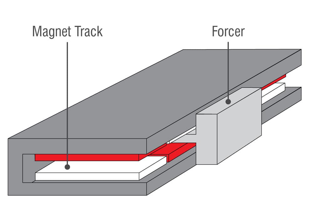 U-shaped ironless linear motor diagram
Ironless linear motors are typically regarded as the optimal drive solution for high precision applications due to their lack of cogging forces. There is a sublety here though; the lack of cogging is only useful for accuracy during movements. If only point to point movements are of concern, ironcore motors are preferred because of higher force density.
Ironless motors were chosen for the LDM because of their lack of cogging and because the lack attraction force minimizes loading and deformation in the stage structure. The LDM’s side mounted motor design would not be possible with an ironcore motor due to the massive attraction forces.
Linear motors also have extremely high axial stiffness when paired with high resolution position feedback. Servo bandwidths up to 100Hz can be achieved without too difficulty, increasing the speed which the servo controller can track setpoint changes and thus decreasing move and settle times. While comparable precision can be achieved with mechanical drive systems, the servo controller must always be detuned to account for the lack of stiffness in the drive system.
Lastly, the reliability of linear motors is unmatched. If treated properly, the lifespan of a linear motor is practically unlimited. Overheating is the only real risk for damage, which can be mitigated with proper driver current limits.
Optical Linear Encoders
 The sin & cos signals of an encoder can be interpolated to achieve extremely high resolution
Modern optical linear encoders are remarkable pieces of technology. The standard 20µm grating pitch can easily be interpolated to 1nm with a 16 bit ADC. Sensors with interpolation accuracy error of >100nm over a 20µm grating pitch is also readily available. The LDM’s controller includes signal offset and gain error compensation parameters to further reduce interpolation error.
LDM stages use an analog encoder interpolated to a default resolution of 1nm. Typically the top speed of nanometer resolution stages is very limited because the position needs to be read at incredibly high frequencies as movement speed increases. However, the LDM gets around this by scaling back the interpolation and decreasing resolution at high speeds. This allows for the combination of 1nm resolution and unlimited top speed, which is unheard of for stages in this category.
Stage Layout
One of the largest differentiating factors between the LDM and similar stages is the side-mounted motor. Most stages have the motor mounted directly in the center. While this is the most space efficient design, it results in significant stiffness losses in the base and carriage. Because the LDM’s motor is located off to the side, the primary structural loop between the mounting surface, bearings, and payload can be kept extemely rigid. Due to their high stiffness, the base and carriage are also much easier to manufacture with extremely tight tolerances, reducing flatness and angular runout errors.
The side motor is also beneficial for encoder placement. The encoder can be mounted much closer to the payload because the motor isn’t in the way. In this case the encoder is centered between the bearings and located as high up as possible without compromising stiffness. The encoder scale is also located much farther away from the motor (heat source), improving thermal stability.
One downside of the side motor design is decreased roll stiffness. Roll stiffness is proportional to the bearing spacing squared. A side mounted motor necessitates moving the bearings closer together for a given form factor. This isn’t quite as ideal for XY applications, but was considered a suitable trade-off.
XY Assemblies
The LDM stage design also includes a couple of handy features for XY assemblies. The base & carriage is designed to mount directly in XY without adaptor plates to maximize system flatness and parallelism. The carriage also includes dowel pin holes for alignment of the top stage, the base of which can be butted up against to obtain perpendicular alignment. These dowel pin holes are machined in the same operation as the bearing surfaces, and hence allow for tight orthogonality tolerances between the uppper and lower stages.
A mounting p-clip on the controller housing is also included for cleanly routing power/data to the top stage. Because controllers are built directly into these stages, only a single 5mm cable needs to be ran between them.
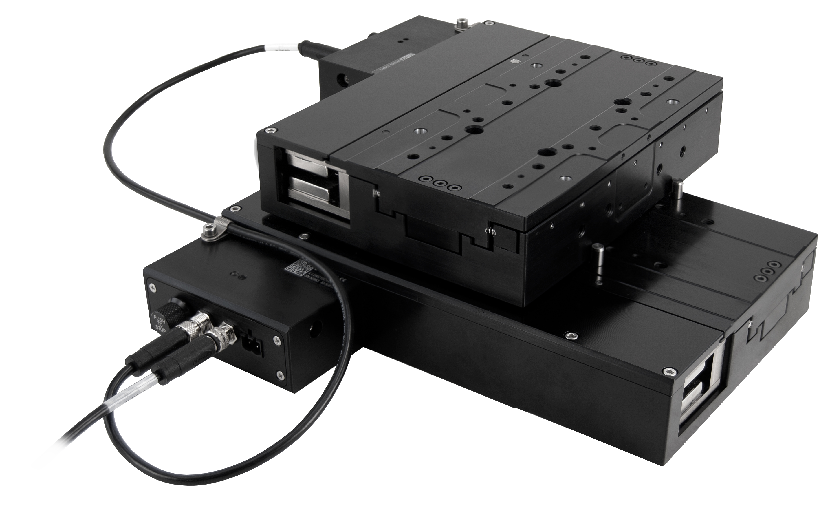 A pair of LDM stages in XY configuration. The integrated controller simplifies cable management, requiring only a single 5mm cable.
Performance
The performance of these stages is remarkable compared to screw driven stages. After applying 64 point calibration with laser interferometer, accuracies of 250nm can be easily achieved over full travel. This accuracy is so good that it’s very difficult to achieve in practice because such tight temperature control is needed. Increasing the length of a 110mm steel encoder scale by 250nm requires only 0.3°C temperature change. For this reason, the LDM’s accuracy specification is listed as 1um to represent a more practically achieveable value.
 Full travel accuracy plot of an LDM110
Unidirectional repeatability can also be measured at under 100nm. The true repeatability floor of these stages is currently unknown because it’s limited by environmental control of the interferometer setup.
In-position jitter comes in around 5-7nm RMS measured at 20KHz with laser interferometer. This ultimately limits the minimum incremental move to around 25nm based on NIST’s evaluation criteria. Interestingly enough, nearly all the jitter is due to current sensor noise in the motor’s PWM current control servo loop. Modifying the current control loop to ignore current feedback and set PWM duty cycle based on motor resistance and inductance results in jitter which is nearly at background levels (approximately 1.5-2nm RMS). Implementing a pure feedforward current controller could be a future improvement for these stages. However, Zaber’s X-MCC external controllers feature improved low noise current sensors, providing an alternative for ultra high precision applications.
 The X-MCC external controller provides low enough jitter that the LDM can produce clearly defined steps under 10nm
Geometric runout performance is excellent for machined components, but does get slightly worse at longer travel lengths; longer parts are relatively more flimsy and tend to distort more during machining. Vertical and horizontal runout typically falls around 2um (60mm travel) to 5um (210mm travel). Angular runout ranges from around 0.002° (60mm travel) to 0.008° (210mm travel). One interesting discovery is that yaw and horizontal runout can be tuned to nearly 0 on all stage lengths if these errors are measured while adjusting preload. More conservative published specs for yaw and horizontal runout were chosen to facilitate less complex assembly processes.
Lessons learned
No project is complete without recognizing what you’ve learned along the way.
- Don’t blindy trust manufacturers spec sheets.
- The first LDM prototypes had around 5um accuracy (similar to existing stepper motor stages with linear encoders). This result seemed odd, as geometric runout errors and repeatability were substantially smaller. It was eventually determined that using an encoder from a different manufacturer increased the accuracy by an order of magnitude. The gotcha is that both of these manufacturers published identical accuracy specs (5um/m). The key was that this statement holds true whether the 5um error is observed over 5mm or 500mm.
- All errors have a source, regardless of how small.
- The performance of LDM stages was so good compared to previous products, it actually unmasked a few rounding errors in firmware that were too small to be observed on any other product. These were initially thought to be due to random temperature fluctuations, but digging deeper ultimately revealed firmware bugs.
- Milling machines are quite accurate, usually fixturing is the problem.
- The vast majority of geometric errors observed in LDM carriages and bases were due to part deflections during machining. Improving fixturing methods was the key to hitting >10um flatness tolerances.
- Building one of anything is easy. Building 100 is hard.
- It’s really easy to carefully babysit the machining and assembly of an LDM stage to produce a single stage with remarkable geometric accuracy. However, this obviously isn’t feasible for standard production. Be aware of this when building prototypes.
- Laser interferometers aren’t always the best length measurement tool.
- Laser interferometers are very susceptible to atmospheric index of refraction changes for small measurements (>200nm). Linear encoders don’t suffer from this and can be more accurate over small ranges of travel. Capacitive sensors are also an excellent choice.
- Precision and speed isn’t useful without precise timing.
- Original LDM stages didn’t include digital IO. It was quickly realized that timing limitations of the RS232 data connection were a massive handicap for many applications. 1nm position readout at 300mm/s is only useful if you can coordinate 3rd party devices with excellent timing.
Conclusion
LDM stages provide a unique addition to Zaber’s motion control lineup and the motion control industry as a whole. These stages have increased the precision Zaber can offer from a linear stage by nearly an order of magnitude. More importantly, they lower the bar for ultra-precision motion control from both a price and ease of use standpoint. A user with almost no motion control experience can have one of these stages performing 25nm moves in a matter of minutes.
Note: The content of this article is intentionally limited to respect confidential information of Zaber Technologies.
