
I had previously 3D printed a tensegrity structure, and thought it would be fun to machine a couple as Christmas presents for my parents. The 3D printed ones are a little flimsy, but I figured steel cables would make these much stiffer.
Design
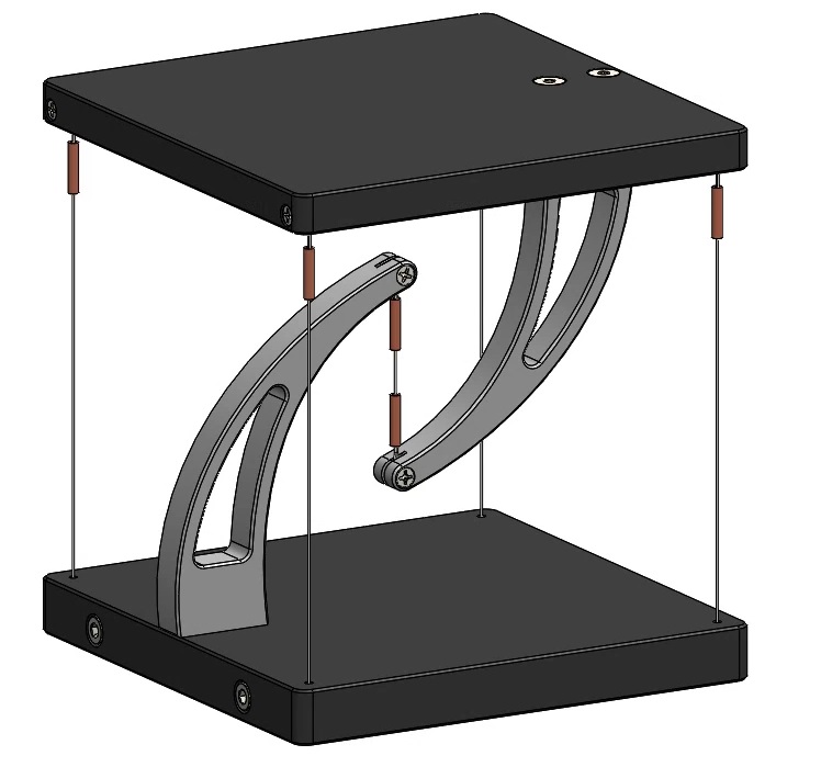
The design was reasonably straightforward. All the parts were to be made from 6061-T6 aluminum to keep machining simple. I wanted the structure to comfortably hold a coffee mug, so went with 100mm X 100mm outer dimensions. Making the curves on the arms look fluid was surprisingly tough. I ended up using splines, which are not ideal for manufacturability, but that was future Graham’s problem.
The most complicated part of the design was the tensioning mechanism. Each of the 4 outer wires needs to be adjusted independently to level the platform. Packaging all 4 adjusters into the base was tough. Notice how the wire channel on the far side passes over the adjustment screw for the opposite side. The obvious design is to make the adjusters in an X pattern, but then there’s nowhere to put the adjustment screws (I didn’t want to machine the outer holes into the sides on an angle). The extra washers are to hold each wire down so they stay bent around the curved transition nicely during tensioning.
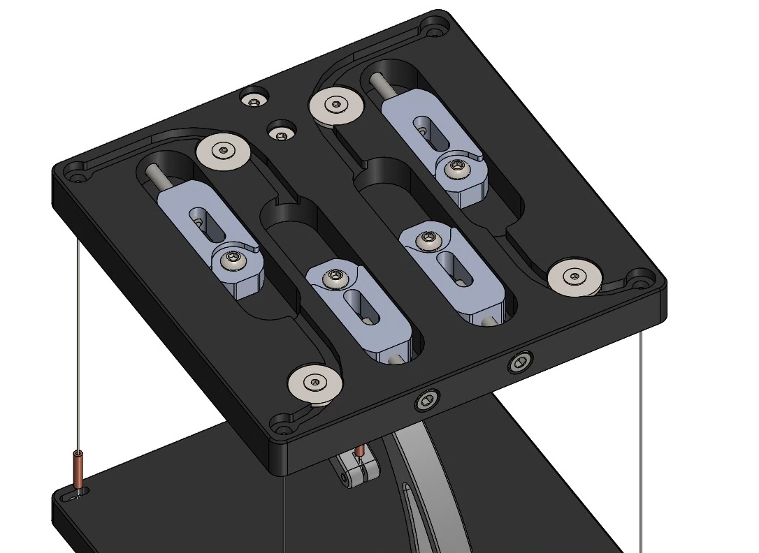
Semi-hardened stainless steel wires of 0.015” diameter were chosen for this design, with a calulated breaking strength of approx 40 lbs. This seems like overkill, but the center wire has to hold the payload, plus tension of the outer four wires. A quick FEA simulation was also run on the arms to confirm they wouldn’t yield below 40lbs. Nicopress miniature wire rope crimps were used to loop the ends of the wires. Apparently these are rated to 100% the breaking strength of the wire.
Machining
Most of the parts were fairly straightforward to machine, but particular care was taken to make them cosmetic; the 6061 aluminum scratches if you look at it wrong. A keen eye will notice the chamfers on the bottom left corner of the arm stock. This was done to give a reference surface to align the arms for drilling holes into the bottom, otherwise it would’ve been hard to get them straight.
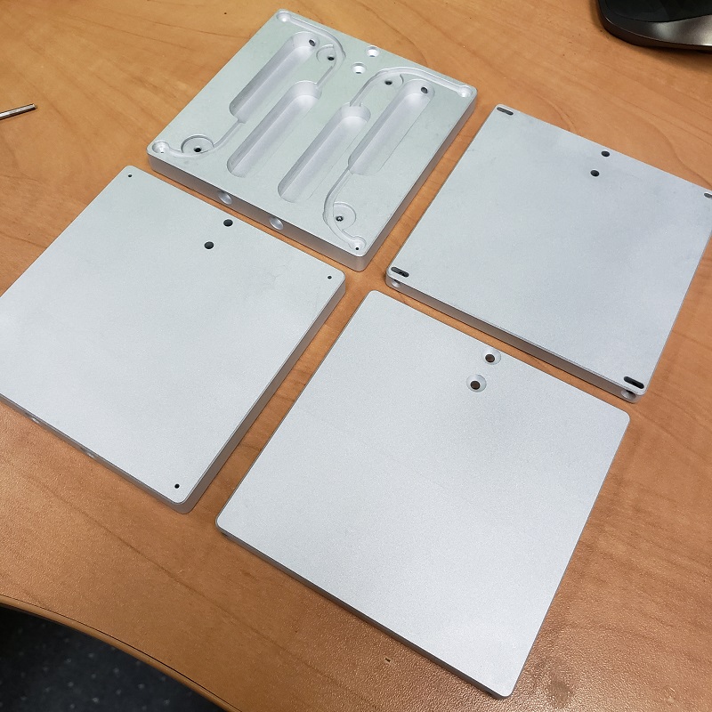
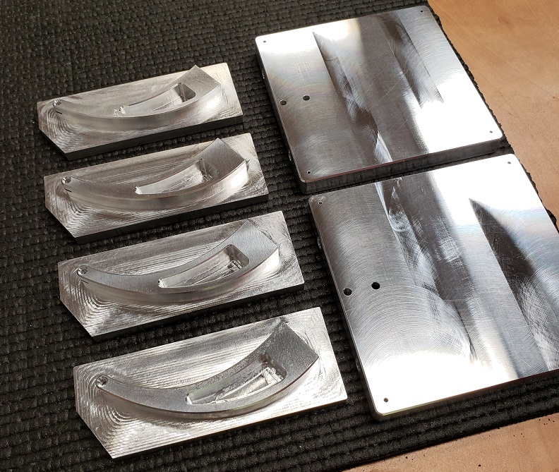 These parts were pretty straightforward.
The arms were by far the toughest part to make. A set of custom soft jaws had to be made to hold them for the final operation. I was worried the jaws would crush them, but they fit so well it wasn’t a problem. The hole on the jaws is for zeroing the machine in XY, as there isn’t a single square edge to pick up on the arm itself. Making the arm curves from splines also meant that CAD modelling the jaws was a pain, but oh well.
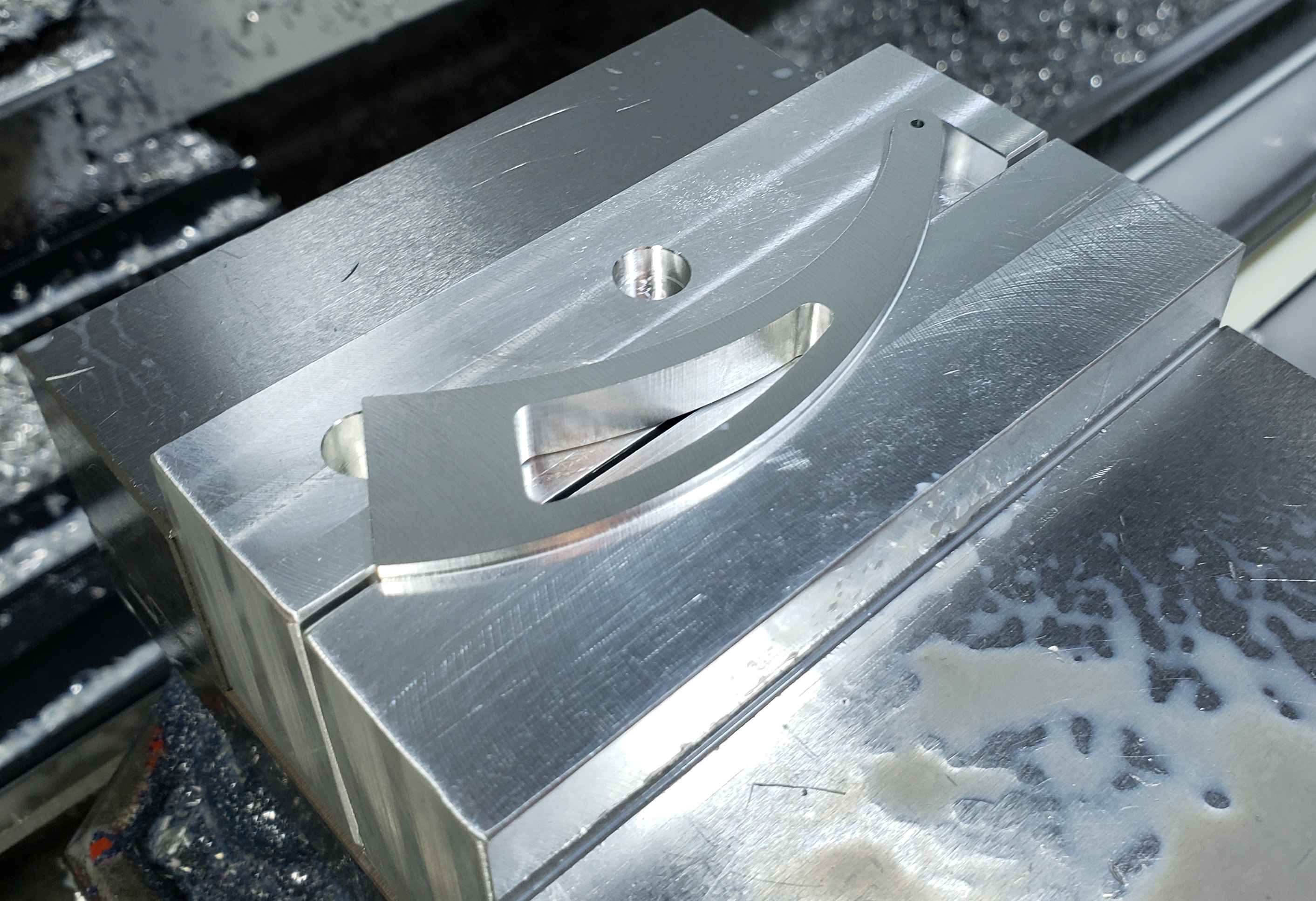 Final operation on the arms with custom soft jaws
Finishing
After all the parts were machined, a test build was done prior to finishing to make sure everything fit. The structure was a huge pain to assemble, but once the wires were tensioned it was incredibly stiff. These platforms are least stiff in yaw, and even that was very impressive.
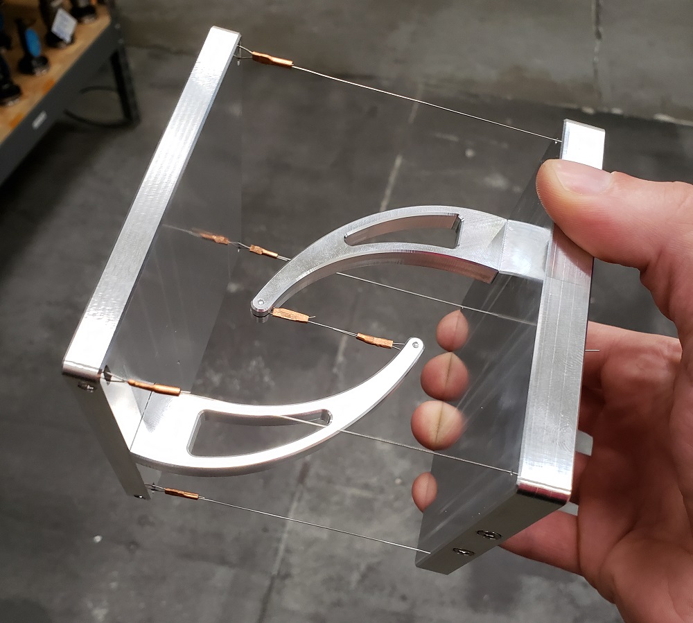 The platform doesn’t visibly deflect when held sideways. Super cool.
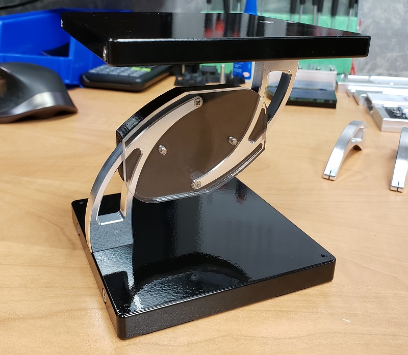
Instead of anodizing these parts, I wanted to try spray painting them to get a glossy finish and try something new. Spray painting turned out to be a huge pain, but the end result looked pretty good. The parts were glass bead blasted to give the paint a more coarse surface to adhere to. Bead blasting actually leaves a really nice finish on aluminum parts, similar to what you’d find on a Macbook Pro. My only mistake was not plugging the threaded holes. I had to re-tap all of them to get the junk out.
 Bead blasting the parts yields a “Macbook pro” surface finish.
The parts were then spray painted in the following order: self-etching primer, gloss-black, gloss-clear. I wasn’t planning on the clearcoat but the black scratches instantly without it. This process turned out to be really time consuming.
Final Product
One idea that turned out to work great was a 3D printed jig and laser cut acrylic clamp to hold the arms in place while installing the outer four wires. This jig turned out to be a huge improvement; the assembly process went from being incredibly difficult to straightforward.
 This 3D printed assembly jig made the structures easy to assemble.
I’m really happy with how these turned out. The structures are remarkably stiff, and can easily hold a full cup of coffee without fear. They also look really good too. The spray painting, although a huge pain, also looks really good. It’s nearly a mirror finish.
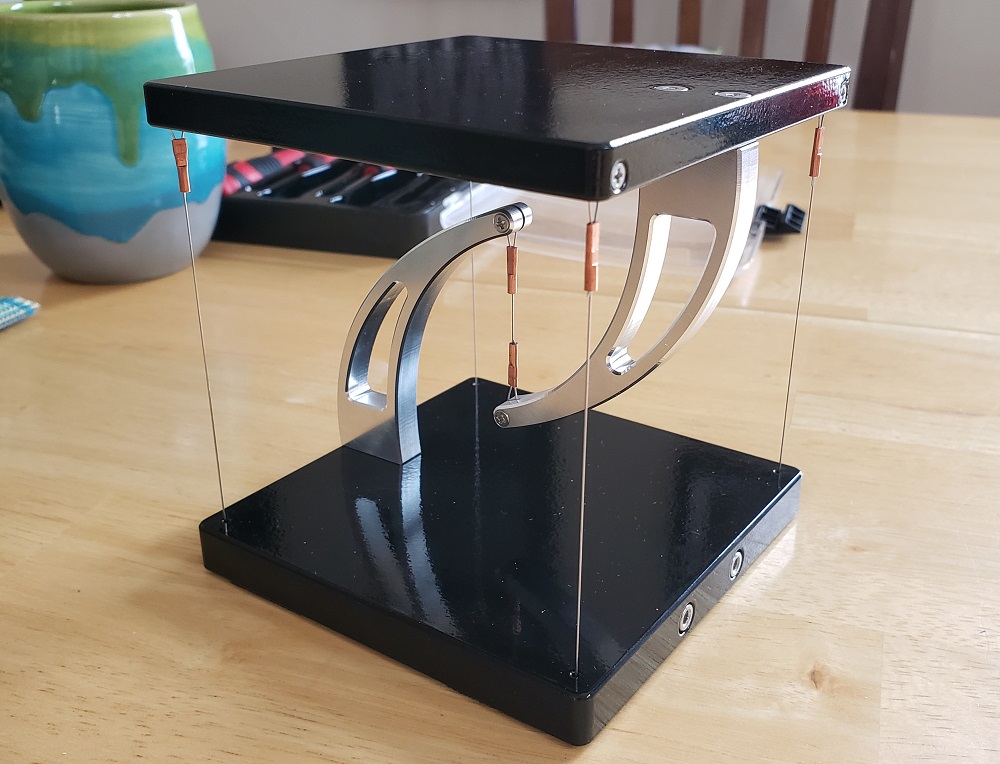 The finished tensegrity structure.
Future Improvements
Changes I would make next time:
- Spray Painting
- If the parts are aluminum just get them anodized. It’s so much easier, and probably more durable.
- Screw Lengths
- I ended up having to grind down a few screws to mount the arms because I hastily picked a length that wasn’t very common. I knew not to do this, but it never hurts to re-iterate.
- Bead Blasting
- Plug threaded holes with screws prior to bead blasting.
Overall I don’t think there’s much I’d do differently about the design of these. The design could obviously be optimized for maximum machinability, but that wasn’t the focus.
